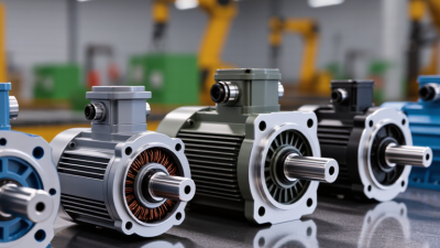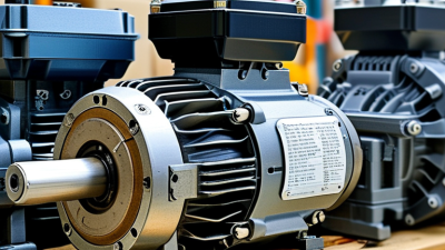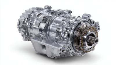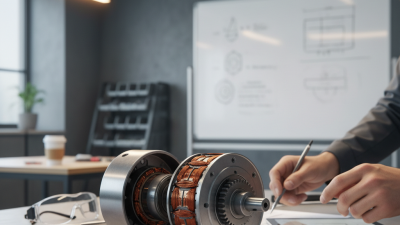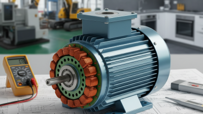

A Break Motor, more accurately called a brake motor, combines an electric motor with a mechanical stopping system. It drives equipment, then holds the shaft when electrical power disappears. This design supports cranes, hoists, conveyors, machine tools, and automated doors. Picture a conveyor stopping beside a loading station. The motor stops turning, while friction discs hold the load securely.
The term “Break Motor” appears often in searches, although “brake motor” is the accepted engineering spelling. That small distinction matters. A vague definition can hide serious selection risks. Most brake motors use a spring-applied, electrically released brake. When the coil receives power, it pulls the armature away from the friction surface. The shaft rotates. When power is removed, springs press the friction surfaces together. The shaft stops and remains held.
The U.S. Department of Energy reports that motor-driven systems consume more than half of industrial electricity in the United States. Its Improving Motor and Drive System Performance guidance shows why efficient motor selection deserves attention. The International Energy Agency has also estimated that electric motor systems use roughly 43–46% of global electricity. These figures include many systems that need controlled stopping, not just continuous rotation. A brake motor can improve operational control, but it is not automatically energy efficient. Brake wear, stopping frequency, load inertia, and thermal limits still require calculation. Details matter. IEC 60034 standards and NEMA MG 1 provide useful reference points for motor performance and construction. In practice, the safest choice depends on the actual load, duty cycle, environment, and required stopping time. I may simplify one point: a brake motor does not replace a complete safety system. It is one carefully selected component.
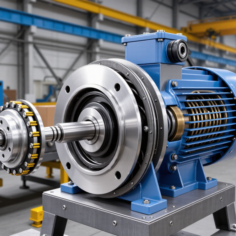
A brake motor is an electric motor fitted with a mechanical braking system. It stops and holds a load when electrical power is removed. This differs from a standard motor, which may continue coasting. In workshops, technicians use brake motors where accurate stopping matters. Think conveyors, hoists, mixers, and machine tools. The brake is not an optional decoration.
A typical unit combines a motor, brake disc, springs, and an electromagnet. When power reaches the motor, the electromagnet releases spring pressure. The shaft can rotate. When power is cut, the springs press the friction surfaces together. This creates stopping torque and holds the shaft. Some designs use a separate brake supply or rectifier, so voltage checks matter. Never judge performance by sound alone.
Selection depends on load, speed, stopping frequency, shaft position, and required holding torque. A brake motor may stop quickly, but it is not automatically a safety device for every application. Heat can build during repeated stops. Dust, moisture, worn friction surfaces, or incorrect adjustment can increase stopping distance. I have seen users blame the motor when the real issue was an oversized load or poor maintenance. That assumption deserves review. Measure actual stopping time and inspect the air gap according to the service manual. Test under controlled conditions, with guards fitted and power isolated during inspection.
A brake motor combines an electric motor with a spring-applied electromagnetic brake. When power is supplied, the brake releases and the motor rotates. When power is removed, the springs apply the brake and stop or hold the shaft.
The chart shows a representative operating sequence using normalized motor speed and brake status. Actual stopping time depends on the load, motor inertia, brake torque, supply voltage, and brake design.
A “break motor” usually refers to a brake motor, an electric motor with an integrated stopping mechanism. Its motor creates rotation, while the brake holds or stops the shaft when power is removed. This design is common in lifting equipment, conveyors, machine tools, and automated doors. The brake is not simply an extra switch.
The main components include the stator, rotor, shaft, and brake assembly. The stator produces a rotating magnetic field. The rotor follows this field and turns the shaft. Inside the brake assembly, an electromagnetic coil releases the friction disc when energized. Springs press the disc against a fixed surface when power disappears. This spring-applied action helps prevent unwanted movement during a power interruption. The friction disc needs clean, even contact. Dust or oil can reduce braking performance.
A rectifier may convert incoming alternating current for the brake coil. The brake housing protects the internal parts, while a cooling fan controls motor temperature during repeated cycles. Some designs include manual release hardware for maintenance or emergency positioning. A technician checks the air gap, disc thickness, coil voltage, and unusual noise during inspection. Small changes matter. A clicking sound may indicate normal engagement, but grinding can suggest wear or misalignment. It is tempting to assume the motor and brake wear equally. They do not. Frequent starts increase brake wear, while heavy loads often stress the motor and shaft more severely. Manufacturers’ service data should guide adjustments, because incorrect brake clearance can cause delayed stopping or excessive heat.
A brake motor combines an electric motor with a fail-safe stopping brake. The motor creates rotation through electromagnetic force. The brake controls that rotation when power disappears. The International Energy Agency reports that electric motors consume about 45% of global electricity. Efficient braking therefore supports safer and more controlled industrial operation.
How a brake motor operates step by step is straightforward. First, the motor receives electrical power and accelerates the shaft. At the same time, an energized brake coil creates a magnetic field. This field pulls the armature away from the friction disc. The shaft can then rotate freely. When the control circuit cuts power, the magnetic field collapses. Springs push the armature against the disc. Friction stops the shaft, often within a defined stopping time. A rectifier may convert incoming AC power for the brake coil. IEC 60034 standards help define motor performance and protection requirements, but application conditions still matter.
Tips: Check the air gap regularly. Measure stopping time under real load. Inspect the friction surface for dust, heat marks, or uneven wear. The quoted IEA figure describes motors generally, not every brake motor. That distinction matters. In practice, stopping performance can change with load, temperature, and voltage. My field experience suggests installation errors are often overlooked. A correct motor can still brake poorly when alignment or adjustment is wrong.
What Is a Brake Motor and How Does It Work?
A brake motor combines a standard electric motor with a braking unit. The motor creates rotation, while the brake stops or holds the shaft. In many designs, an electromagnetic coil releases spring pressure when power reaches it. When power disappears, the springs press friction discs together. The shaft stops quickly and remains locked. This fail-safe action is useful on hoists, conveyors, mixers, and lifting equipment.
Common Types of Brake Motors
Spring-applied electromagnetic brake motors are widely used in industrial machinery. They usually include friction discs, springs, an armature plate, and an electric coil. These motors can use an alternating-current or direct-current brake coil. A direct-current coil often provides smoother engagement, while an alternating-current coil may simplify certain control systems. The correct choice depends on voltage, stopping frequency, load inertia, and available control equipment.
Permanent-magnet brake motors offer compact braking for smaller machines. Their magnets create holding force without continuous coil power. They often suit indexing equipment, small conveyors, and positioning systems. Hydraulic brake motors use fluid pressure to engage or release braking components. They can handle demanding loads, but they require more parts and careful maintenance. Some systems also use a separate mechanical brake beside the motor.
Selection is not always obvious. A brake that stops an empty shaft may struggle with a loaded drum. Heat, dust, moisture, and repeated starts can change performance. I have found that checking stopping time under real load is more reliable than trusting a catalog estimate. Even brake adjustment matters. A small air gap error can produce noise, drag, or delayed stopping.
A brake motor combines an electric motor with a spring-applied braking system. When power is supplied, an electromagnetic release lifts the brake. The shaft can then rotate. When power stops, springs press the brake disc against a friction surface. The motor stops and holds its load. This action is especially useful where uncontrolled movement could damage equipment or injure workers.
Typical applications include conveyor systems, lifting equipment, packaging machines, machine tools, and automated doors. Conveyors need controlled stopping during jams or power interruptions. Hoists require secure holding when a load is suspended. Machine tools benefit from short stopping times during repeated production cycles. Selecting the motor requires checking load weight, stopping frequency, shaft speed, installation position, and required stopping time. A brake that is too small may overheat.
Maintenance should follow the equipment manual and local safety procedures. Isolate electrical power before opening the brake housing. Check the friction lining for uneven wear, oil, or glazing. Measure the air gap with a suitable gauge. Listen for scraping sounds and watch for delayed stopping. Inspect springs, wiring, fasteners, and the brake rectifier. Dust can hide early damage. A clean visual check may still miss a worn friction surface. That is an easy mistake. Record stopping distance, operating temperature, and inspection dates. Qualified technicians should adjust or replace internal components, especially on lifting equipment.
| Data Dimension | Typical Specification or Description | Practical Significance |
|---|---|---|
| Definition | A brake motor is an electric motor integrated with a mechanical brake, usually mounted on the non-drive end of the motor. | It provides both rotational power and controlled stopping or holding in one compact assembly. |
| Common Motor Type | Three-phase squirrel-cage induction motors are widely used; single-phase versions are also available for smaller equipment. | The motor type determines starting performance, efficiency, control method, and available power ratings. |
| Brake Operating Principle | In a common spring-applied, electrically released design, springs press friction surfaces together when power is removed. Energizing the brake coil releases the brake. | The load is automatically held when electrical power is interrupted, subject to correct sizing and installation. |
| Alternative Brake Design | Some systems use a power-applied brake, which engages when the brake coil is energized and releases when power is removed. | The fail-safe behavior differs, so the design must match the machine’s safety requirements. |
| Main Brake Components | Typical parts include a brake coil, friction disc, armature plate, springs, hub, brake housing, and manual release mechanism. | Wear, contamination, incorrect air gaps, or coil faults can reduce braking performance. |
| Stopping Action | When the motor is switched off, the brake engages after a short mechanical and electrical response time. Exact stopping time depends on inertia, load, brake torque, and control circuitry. | A brake motor can stop a shaft more quickly than allowing the motor to coast, but it is not automatically a substitute for a regenerative or dynamic braking system. |
| Holding Function | The brake can hold a stationary load when its rated static holding torque exceeds the external load torque with an appropriate safety margin. | Correct torque selection is essential for vertical axes, hoists, lifts, and other suspended or back-driving loads. |
| Typical Brake Torque Range | Small industrial brake motors commonly use brake torques from a few N·m to several hundred N·m. The exact value is determined by motor frame size and brake design. | Brake torque should be selected from the manufacturer’s rating rather than estimated only from motor power. |
| Common Power Range | Industrial brake motors are commonly available from fractional-kilowatt ratings to many tens of kilowatts, with larger custom systems also possible. | Power, speed, duty cycle, load inertia, and starting frequency must all be considered during selection. |
| Brake Voltage | Brake coils may operate on AC or DC. A rectifier is often used to supply a DC brake coil from an AC motor circuit. | The coil voltage, rectifier type, switching method, and polarity must match the motor control circuit. |
| Motor Control Compatibility | When used with a variable-frequency drive, the brake coil usually requires separate control, and the drive may need a controlled stop sequence. | Improper sequencing can cause the brake to engage while the motor is still rotating or release before sufficient torque is available. |
| Typical Applications | Conveyors, machine tools, packaging equipment, cranes, hoists, elevators, material-handling systems, doors, winches, and indexing machinery. | These applications benefit from rapid stopping, repeatable positioning, or load holding during shutdown. |
| Vertical Load Suitability | Brake motors can be used for vertical loads when the brake, gearbox, shaft, coupling, and control system are correctly rated. | A brake should not be treated as the only protective measure where uncontrolled descent could cause injury or major damage. |
| Inspection Frequency | Inspect according to duty cycle, environment, and safety requirements. High-cycle or critical equipment generally requires more frequent checks than lightly used machinery. | A documented preventive-maintenance schedule helps identify wear before braking performance becomes unsafe. |
| Friction Disc Inspection | Check lining thickness, cracks, glazing, uneven wear, oil contamination, and discoloration caused by overheating. | Replace worn or contaminated friction components; do not apply lubricant to friction surfaces unless explicitly permitted by the design. |
| Air Gap Check | Measure the gap between the armature plate and the brake body using the procedure and limits specified for the particular brake. | An excessive gap may prevent complete release, while an incorrect gap can increase drag, heat, and wear. |
| Electrical Checks | Verify coil resistance, supply voltage, rectifier condition, terminal tightness, insulation condition, and correct release current. | Low voltage may cause incomplete release, while excessive voltage or poor switching can overheat the coil. |
| Mechanical Inspection | Check mounting bolts, shaft keys, hub fit, bearings, couplings, manual release hardware, and signs of abnormal vibration. | Loose or misaligned components can create noise, uneven braking, shaft damage, and premature failure. |
| Thermal Management | Keep cooling passages clean and prevent excessive braking frequency, prolonged slip, or operation beyond the rated duty cycle. | Excessive heat accelerates friction-material wear and can damage seals, bearings, insulation, and brake coils. |
| Environmental Protection | Select suitable enclosure and protection against dust, moisture, chemicals, washdown, and explosive atmospheres where applicable. | Environmental contamination can reduce friction, corrode parts, block cooling, and compromise electrical insulation. |
| Safety Precautions | Disconnect and lock out electrical power, isolate stored energy, support suspended loads, and verify zero movement before servicing. | A brake motor may fail to hold a load during maintenance if the brake is damaged, manually released, or incorrectly adjusted. |
| Replacement Decision | Replace brake components when wear limits, coil-test limits, structural damage, or repeated overheating are identified. | Use compatible parts and restore the specified air gap, torque, voltage, and release mechanism before returning the equipment to service. |
Note: Specifications described as typical vary by motor size, brake construction, duty cycle, control method, and operating environment. Always verify final values against the applicable equipment documentation and safety requirements.
0086-13586199782